An Werktagen vor 14:00 Uhr bestellt = noch am selben Tag versendet. 30 Tage Bedenkzeit 1 Jahr Garantie

Schaltplan und Codebeispiel

So schließt du den LED-Matrix-Modul MAX7219 Blau an einen Arduino UNO oder ESP32 an, mit einem Beispiel-Sketch, den du direkt hochladen kannst.

MAX7219 8x8 LED-Matrix-Display-Demo

Dieses Projekt zeigt, wie man eine 8x8 LED-Matrix mit dem MAX7219-Treiberchip ansteuert. Der Sketch aktiviert die Matrix, stellt eine angenehme Helligkeitsstufe ein und animiert einen hüpfenden Punkt über alle Zeilen und Spalten.

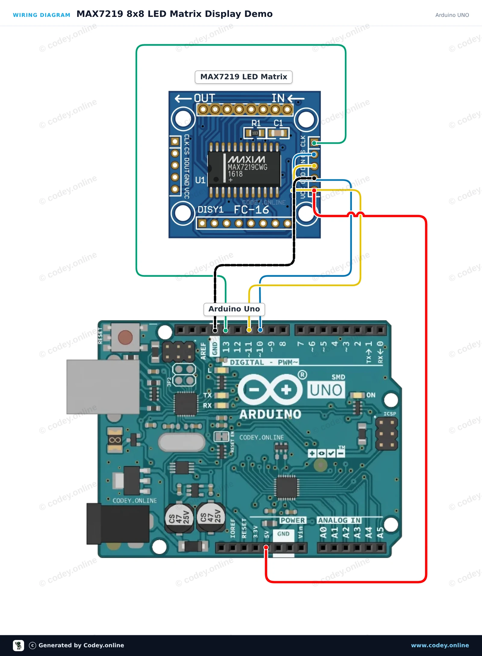
Anschlussplan: LED-Matrix-Modul MAX7219 Blau an einem Arduino UNO
Anschlussplan · Zum Vergrößern klicken
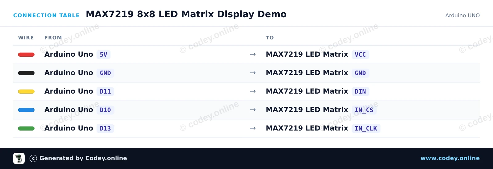
Anschlusstabelle: LED-Matrix-Modul MAX7219 Blau an einem Arduino UNO
Anschlusstabelle · Zum Vergrößern klicken
MAX7219_8x8_LED_Matrix_Display_Demo.ino · kompiliert und getestet
/*
 * ==================================================================
 *  Generated by Codey.online  —  https://www.codey.online
 * ==================================================================
 *  Project   : MAX7219 8x8 LED Matrix Display Demo
 *  Board     : Arduino UNO (arduino:avr:uno)
 *  Parts     : LED Matrix Module MAX7219
 *  Libraries : LedControl 1.0.6
 *
 *  Codey Online is an AI-powered browser IDE for Arduino and ESP32.
 *  Describe your project and Codey writes the code, draws the wiring
 *  diagram and uploads it to your board, straight from the browser.
 *  This code is free to use, modify and share, without warranty.
 * ==================================================================
 */

#include <LedControl.h>

const int DIN_PIN = 11;
const int CLK_PIN = 13;
const int CS_PIN  = 10;

// Create LedControl instance: LedControl(DIN, CLK, CS, number_of_matrices)
LedControl lc = LedControl(DIN_PIN, CLK_PIN, CS_PIN, 1);

// 8x8 bitmap for a smile icon
const byte SMILE[8] = {
  B00111100,
  B01000010,
  B10100101,
  B10000001,
  B10100101,
  B10011001,
  B01000010,
  B00111100
};

// 8x8 bitmap for a heart icon
const byte HEART[8] = {
  B00000000,
  B01100110,
  B11111111,
  B11111111,
  B01111110,
  B00111100,
  B00011000,
  B00000000
};

void drawBitmap(const byte bitmap[]) {
  for (int row = 0; row < 8; row++) {
    lc.setRow(0, row, bitmap[row]);
  }
}

void setup() {
  Serial.begin(115200);
  
  // Wake up MAX7219 from power-saving mode
  lc.shutdown(0, false);
  // Set medium brightness (0 to 15)
  lc.setIntensity(0, 6);
  // Clear the display
  lc.clearDisplay(0);

  Serial.println(F("MAX7219 Matrix initialized!"));
}

void loop() {
  // Display Heart
  drawBitmap(HEART);
  delay(1500);

  // Display Smile
  drawBitmap(SMILE);
  delay(1500);

  // Pixel sweep effect
  lc.clearDisplay(0);
  for (int row = 0; row < 8; row++) {
    for (int col = 0; col < 8; col++) {
      lc.setLed(0, row, col, true);
      delay(25);
      lc.setLed(0, row, col, false);
    }
  }
}

Benötigte Bibliotheken: LedControl 1.0.6

Wiring diagram and example code generated by Codey.online — https://www.codey.online

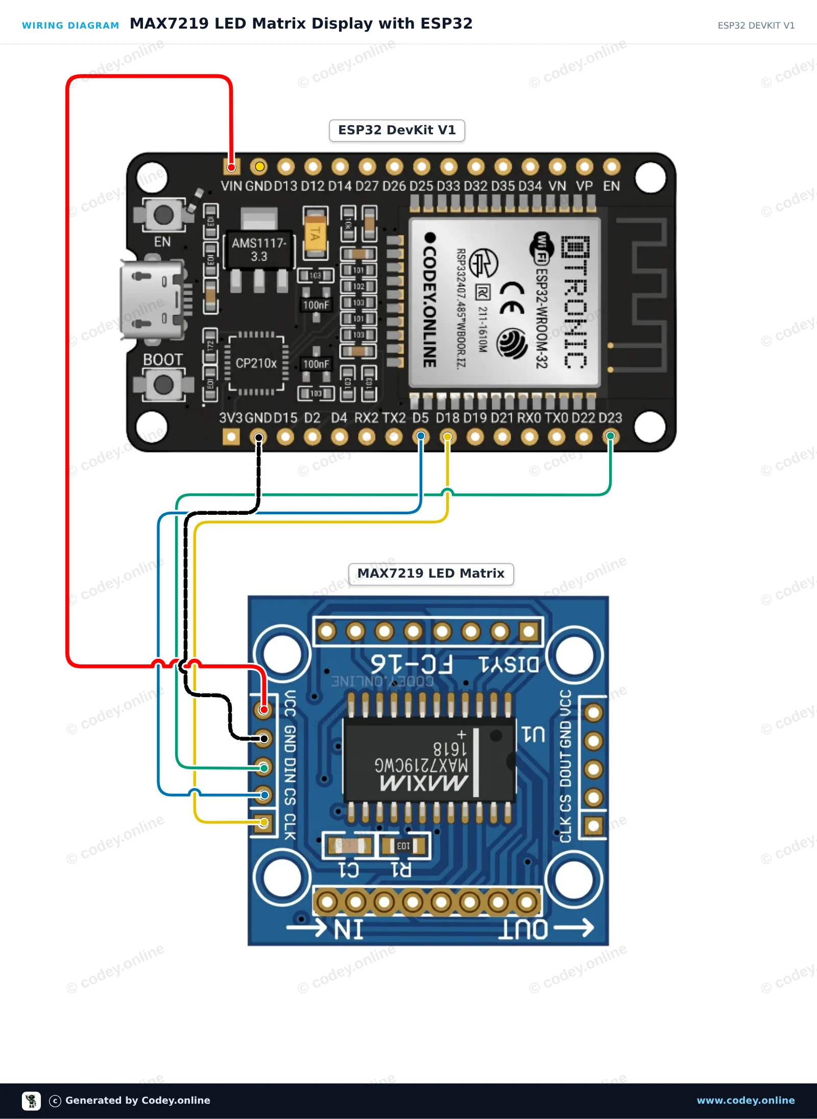
MAX7219 LED-Matrix-Display mit ESP32

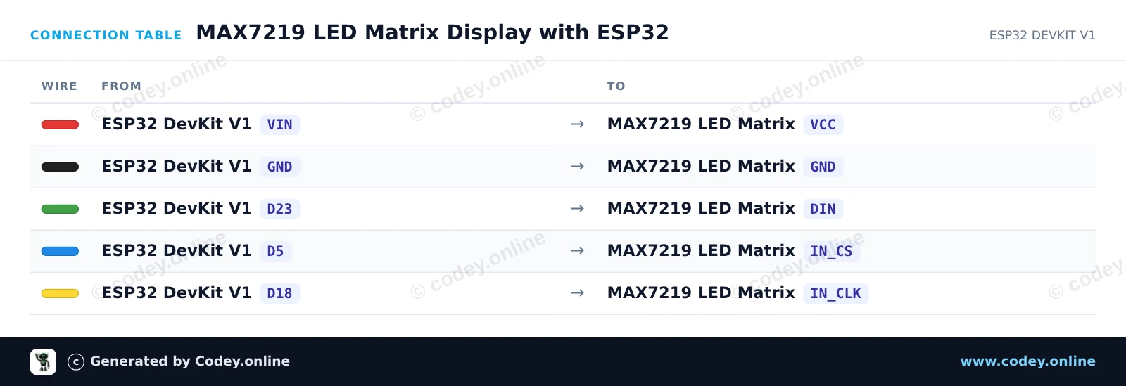
Dieses Projekt zeigt benutzerdefinierte Muster und Animationen auf einem 8x8 MAX7219 LED-Matrixmodul mit Hardware-SPI an. Der ESP32 kommuniziert mit dem Treiber über GPIO 23 (MOSI/DIN), GPIO 18 (SCK/CLK) und GPIO 5 (CS) und versorgt das Display direkt über den 5V VIN-Pin.

Anschlussplan: LED-Matrix-Modul MAX7219 Blau an einem ESP32 DevKit V1
Anschlussplan · Zum Vergrößern klicken
Anschlusstabelle: LED-Matrix-Modul MAX7219 Blau an einem ESP32 DevKit V1
Anschlusstabelle · Zum Vergrößern klicken
MAX7219_LED_Matrix_Display_with_ESP32.ino · kompiliert und getestet
/*
 * ==================================================================
 *  Generated by Codey.online  —  https://www.codey.online
 * ==================================================================
 *  Project   : MAX7219 LED Matrix Display with ESP32
 *  Board     : ESP32 DEVKIT V1 (esp32:esp32:esp32doit-devkit-v1)
 *  Parts     : LED Matrix Module MAX7219
 *  Libraries : none (built-in)
 *
 *  Codey Online is an AI-powered browser IDE for Arduino and ESP32.
 *  Describe your project and Codey writes the code, draws the wiring
 *  diagram and uploads it to your board, straight from the browser.
 *  This code is free to use, modify and share, without warranty.
 * ==================================================================
 */

#include <SPI.h>

const int CS_PIN = 5;

// MAX7219 register addresses
const byte REG_NOOP      = 0x00;
const byte REG_DECODE    = 0x09;
const byte REG_INTENSITY = 0x0A;
const byte REG_SCANLIMIT = 0x0B;
const byte REG_SHUTDOWN  = 0x0C;
const byte REG_DISPTEST  = 0x0F;

// Bitmaps for 8x8 graphics
const byte smile[8] = {
  0b00111100,
  0b01000010,
  0b10100101,
  0b10000001,
  0b10100101,
  0b10011001,
  0b01000010,
  0b00111100
};

const byte heart[8] = {
  0b00000000,
  0b01100110,
  0b11111111,
  0b11111111,
  0b11111111,
  0b01111110,
  0b00111100,
  0b00011000
};

void writeRegister(byte reg, byte data) {
  digitalWrite(CS_PIN, LOW);
  SPI.transfer(reg);
  SPI.transfer(data);
  digitalWrite(CS_PIN, HIGH);
}

void clearDisplay() {
  for (byte row = 1; row <= 8; row++) {
    writeRegister(row, 0x00);
  }
}

void drawBitmap(const byte bitmap[8]) {
  for (byte row = 0; row < 8; row++) {
    writeRegister(row + 1, bitmap[row]);
  }
}

void setup() {
  pinMode(CS_PIN, OUTPUT);
  digitalWrite(CS_PIN, HIGH);

  // Initialize hardware SPI (VSPI: SCK=18, MOSI=23)
  SPI.begin();

  // Configure MAX7219
  writeRegister(REG_DISPTEST, 0x00);  // Normal operation
  writeRegister(REG_SCANLIMIT, 0x07); // Scan all 8 digits/rows
  writeRegister(REG_DECODE, 0x00);    // No BCD decoding (raw matrix mode)
  writeRegister(REG_INTENSITY, 0x04); // Brightness (0x00 to 0x0F)
  writeRegister(REG_SHUTDOWN, 0x01);  // Wake up module

  clearDisplay();
}

void loop() {
  // Display smiley face
  drawBitmap(smile);
  delay(2000);

  // Display heart
  drawBitmap(heart);
  delay(2000);

  // Row sweep animation
  clearDisplay();
  for (byte i = 1; i <= 8; i++) {
    writeRegister(i, 0xFF);
    delay(100);
  }
  for (byte i = 1; i <= 8; i++) {
    writeRegister(i, 0x00);
    delay(100);
  }
}

Wiring diagram and example code generated by Codey.online — https://www.codey.online

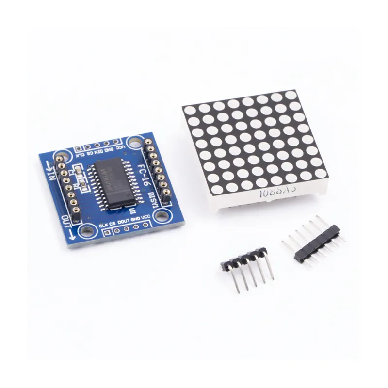
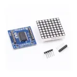
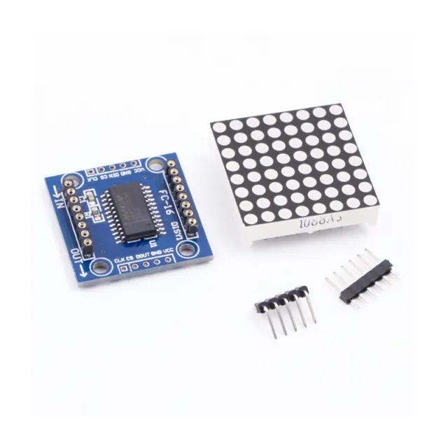
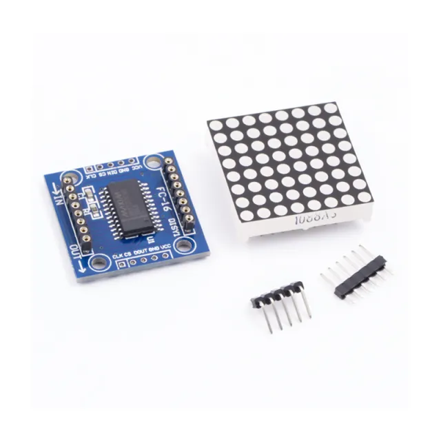
LED-Matrix-Modul MAX7219 Blau

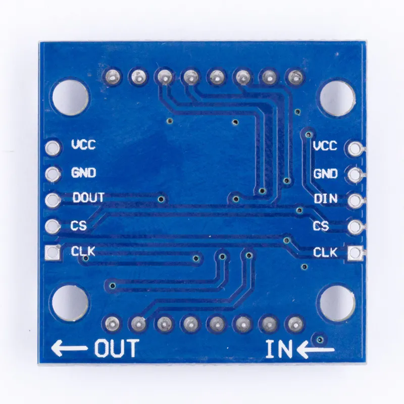
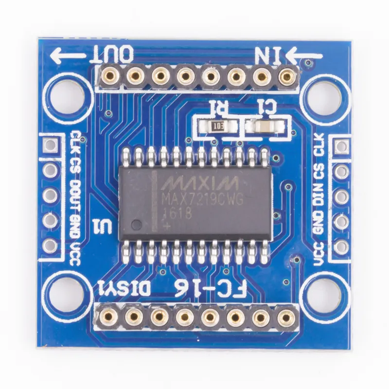
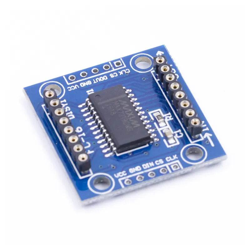
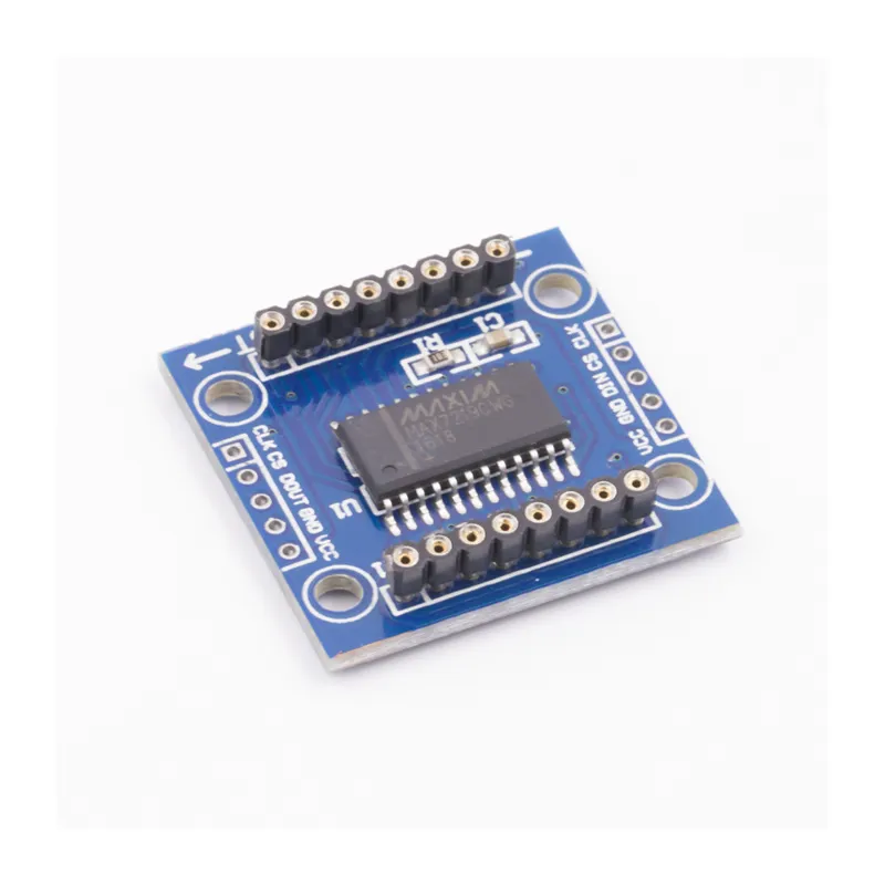
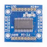
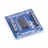
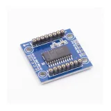
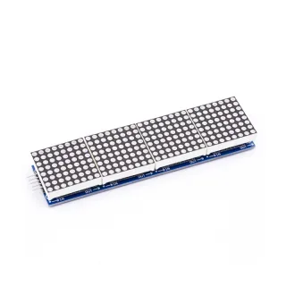
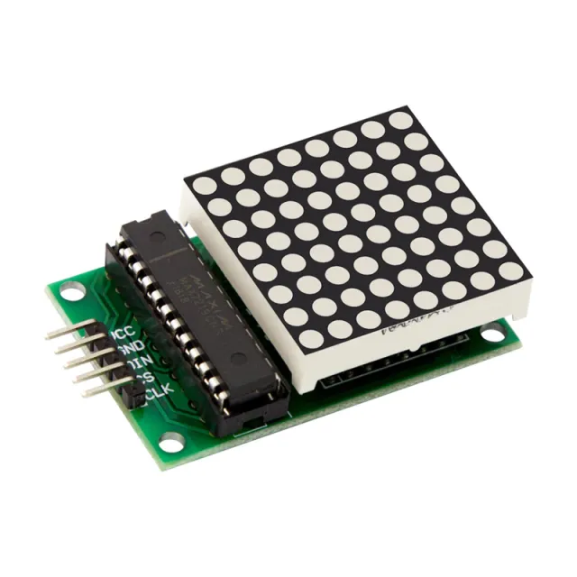
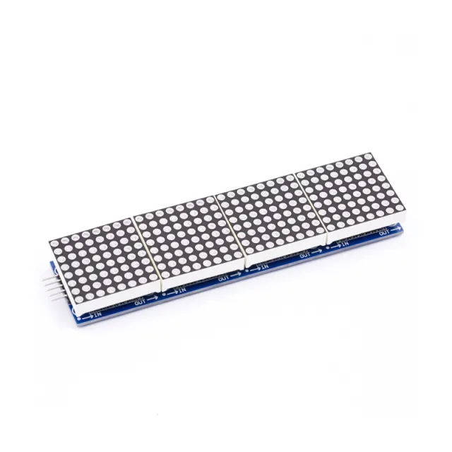
MAX7219 ist ein IC, der zur Ansteuerung von LED-Panels mit gemeinsamer Kathode, 7-Segment-Anzeigen und Pegelanzeigen verwendet wird, die über die SPI-Schnittstelle kommunizieren. Dieses Board hat ein 8x8 Dot-Matrix-LED-Display. Mehrere Module können mithilfe von Header-Verbindungen kaskadiert werden.

Spezifikationen:

  • 8x8 gemeinsames Kathoden-Display
  • Betriebsspannung: 5V
  • Betriebsstrom: 250mA (MAX)
  • Logikspannung der Schnittstelle: 5V
  • Schnittstellentyp: SPI
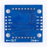
  • Verbindungen: VCC, GND, DIN, CS, CLK
  • Kompatibilität: Kompatibel mit Arduino UNO R3 / Arduino Mega2560.
  • Bibliotheken für Arduino: Max72xxPanel und Adafruit_GFX
  • LED-Farbe: blau
  • LED-Größe: 5 mm
  • Anzahl kaskadierbarer Knoten: 32 (MAX)
  • Treiber-IC: MAX7219
  • Sehr geeignet für Arduino DIY-Projekte
  • Abmessungen: 3,2 cm x 3,2 cm x 1,3 cm
  • 4x3 mm Befestigungsbohrungen
  • 8x8-Matrix
  • MAX7219-Treiber
  • SPI-Schnittstelle
  • Arduino-kompatibel

Warum dieses Produkt wählen?

  • 8x8-Display – Kompaktes LED-Matrix-Display für Projekte.
  • SPI-Verbindung – Funktioniert über die SPI-Schnittstelle.
  • Kaskadierbares Design – Mehrere Module können verbunden werden.
  • Arduino-kompatibel – Geeignet für UNO R3 und Mega2560.
  • Praktische Bibliotheken – Max72xxPanel und Adafruit_GFX enthalten.
Spezifikationen
Abmessungen3,2 cm x 3,2 cm x 1,3 cm
Betriebsspannung5V
KompatibilitätKompatibel mit Arduino UNO R3 / Arduino Mega2560
Treiber-ICMAX7219
Schnittstellenlogikspannung5V
SchnittstellentypSPI
AnschlüsseVCC, GND, DIN, CS, CLK
Arduino-BibliothekenMax72xxPanel und Adafruit_GFX
LED-Farbeblau
LED-Größe5 mm
Anzahl kaskadierbarer Knoten32 (MAX)
Displaytypgemeinsames Kathodendisplay
Befestigungslöcher4 x 3 mm
Arbeitsstrom250mA (MAX)

Bewertungen

★★★★★ 3,5/5 2 Bewertungen
  • ★★★★★Michel Van den AkkerVerifizierter Kauf

    Die Hälfte funktionierte nicht.

  • ★★★★★LBLM LBLMVerifizierter Kauf

    Entspricht meiner Bestellung

Bewertung schreiben
Deine Bewertung

Versand & Rücksendung

Versand

  • Paket mit Sendungsverfolgung€ 6,205 Werktage
  • Paket mit Sendungsverfolgung€ 7,455 Werktage
  • Paket mit Sendungsverfolgung€ 8,655 Werktage
  • Paket mit Sendungsverfolgung€ 9,255 Werktage
Alles zum Versand

Rücksendung

Nicht zufrieden? Du hast 30 Tage nach Erhalt Zeit, das Produkt zurückzusenden.

Alles zur Rücksendung

Zuletzt angesehen

LED Matrix Modul MAX7219 Rot

LED Matrix Modul MAX7219 Rot

€ 2,90
Joystick-Modul

Joystick-Modul

€ 1,65