An Werktagen vor 14:00 Uhr bestellt = noch am selben Tag versendet. 30 Tage Bedenkzeit 1 Jahr Garantie

Schaltplan und Codebeispiel

So schließt du den LED Matrix Modul MAX7219 Rot an einen Arduino UNO oder ESP32 an, mit einem Beispiel-Sketch, den du direkt hochladen kannst.

MAX7219 8x8 LED-Matrix-Display-Demo

Dieses Projekt zeigt, wie man eine 8x8 LED-Matrix mit dem MAX7219 Treiberchip ansteuert. Es initialisiert das Display und zeigt nacheinander ein Smiley, ein Herzsymbol und ein scannendes Pixelmuster an.

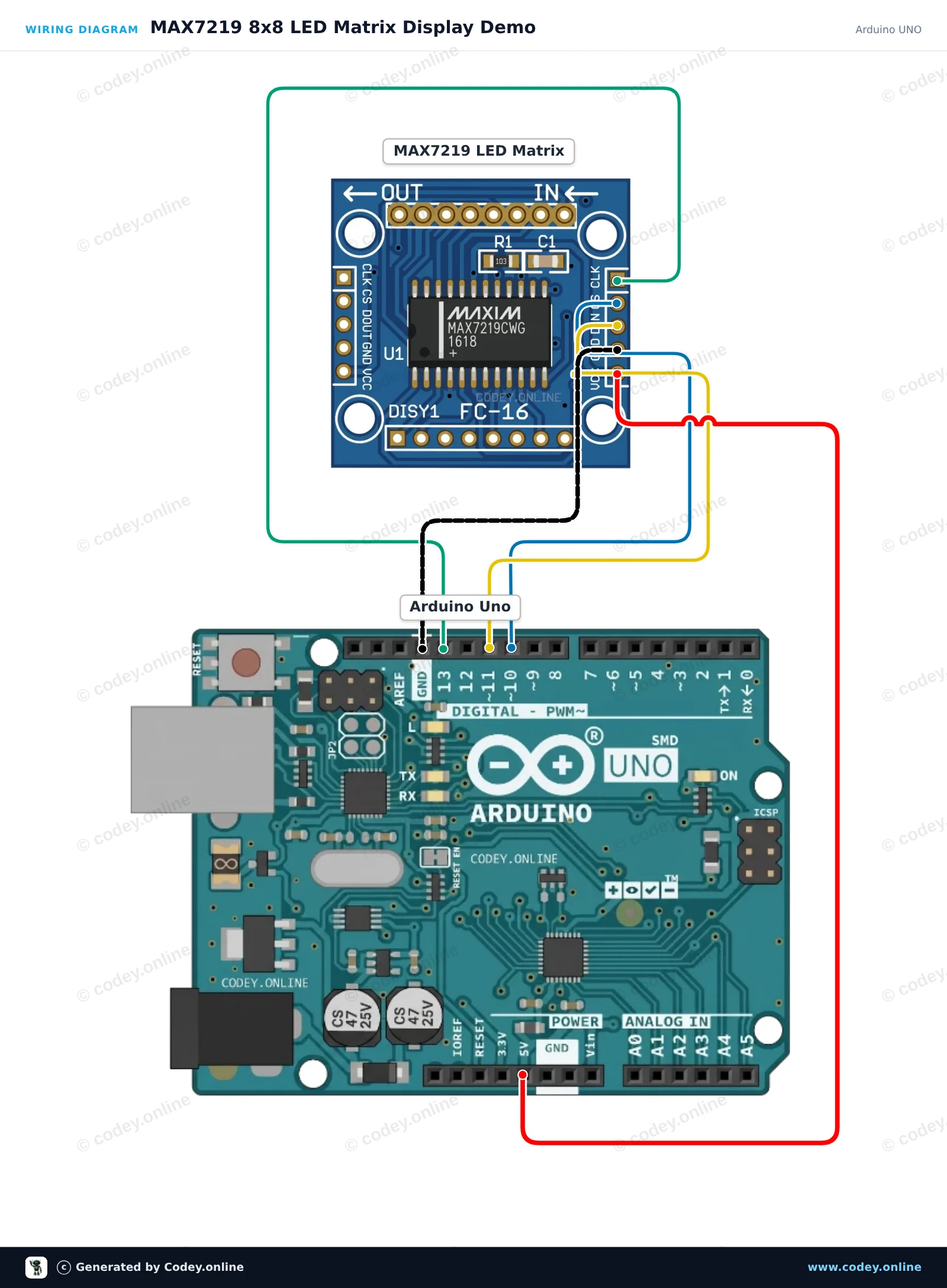
Anschlussplan: LED Matrix Modul MAX7219 Rot an einem Arduino UNO
Anschlussplan · Zum Vergrößern klicken
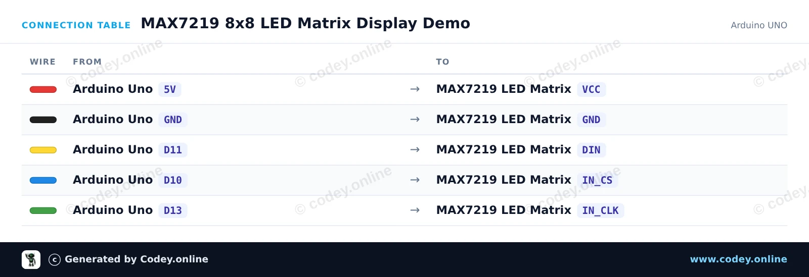
Anschlusstabelle: LED Matrix Modul MAX7219 Rot an einem Arduino UNO
Anschlusstabelle · Zum Vergrößern klicken
MAX7219_8x8_LED_Matrix_Display_Demo.ino · kompiliert und getestet
/*
 * ==================================================================
 *  Generated by Codey.online  —  https://www.codey.online
 * ==================================================================
 *  Project   : MAX7219 8x8 LED Matrix Display Demo
 *  Board     : Arduino UNO (arduino:avr:uno)
 *  Parts     : LED Matrix Module MAX7219
 *  Libraries : LedControl 1.0.6
 *
 *  Codey Online is an AI-powered browser IDE for Arduino and ESP32.
 *  Describe your project and Codey writes the code, draws the wiring
 *  diagram and uploads it to your board, straight from the browser.
 *  This code is free to use, modify and share, without warranty.
 * ==================================================================
 */

#include <LedControl.h>

const int DIN_PIN = 11;
const int CS_PIN  = 10;
const int CLK_PIN = 13;

LedControl lc = LedControl(DIN_PIN, CLK_PIN, CS_PIN, 1);

// 8x8 bitmap patterns
const byte SMILEY[8] = {
  0b00111100,
  0b01000010,
  0b10100101,
  0b10000001,
  0b10100101,
  0b10011001,
  0b01000010,
  0b00111100
};

const byte HEART[8] = {
  0b00000000,
  0b01100110,
  0b11111111,
  0b11111111,
  0b01111110,
  0b00111100,
  0b00011000,
  0b00000000
};

void drawPattern(const byte pattern[8]) {
  for (int row = 0; row < 8; row++) {
    lc.setRow(0, row, pattern[row]);
  }
}

void setup() {
  Serial.begin(115200);
  Serial.println(F("MAX7219 LED Matrix Demo"));

  lc.shutdown(0, false);  // Wake up display
  lc.setIntensity(0, 5);  // Brightness (0-15)
  lc.clearDisplay(0);
}

void loop() {
  // Show smiley face
  drawPattern(SMILEY);
  delay(2000);

  // Show heart
  drawPattern(HEART);
  delay(2000);

  // Clear display
  lc.clearDisplay(0);
  delay(500);

  // Scan a single pixel across all rows and columns
  for (int row = 0; row < 8; row++) {
    for (int col = 0; col < 8; col++) {
      lc.setLed(0, row, col, true);
      delay(30);
      lc.setLed(0, row, col, false);
    }
  }
  delay(500);
}

Benötigte Bibliotheken: LedControl 1.0.6

Wiring diagram and example code generated by Codey.online — https://www.codey.online

MAX7219 LED-Matrixdisplay-Demo

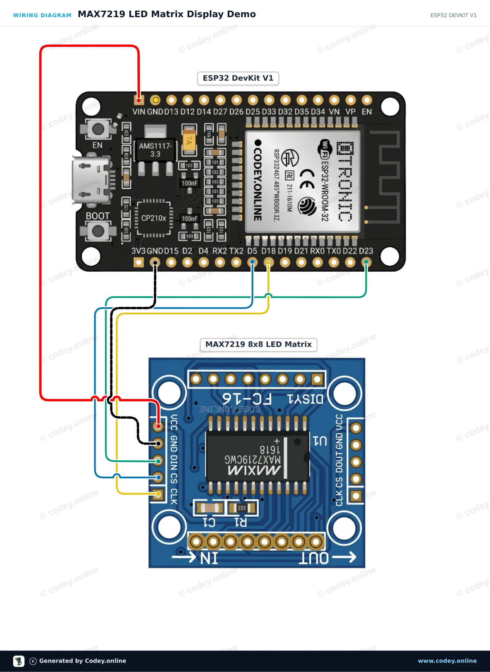
Dieses Projekt zeigt, wie ein 8x8 MAX7219 LED-Matrixdisplay über die hardwareseitige SPI-Schnittstelle des ESP32 angesteuert wird. Der Sketch initialisiert die Display-Register und wechselt zwischen der Anzeige eines Herzsymbols und eines Smileys.

Anschlussplan: LED Matrix Modul MAX7219 Rot an einem ESP32 DevKit V1
Anschlussplan · Zum Vergrößern klicken
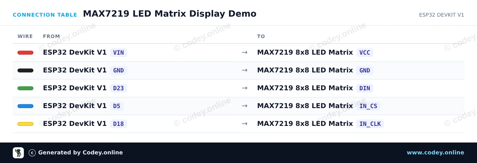
Anschlusstabelle: LED Matrix Modul MAX7219 Rot an einem ESP32 DevKit V1
Anschlusstabelle · Zum Vergrößern klicken
MAX7219_LED_Matrix_Display_Demo.ino · kompiliert und getestet
/*
 * ==================================================================
 *  Generated by Codey.online  —  https://www.codey.online
 * ==================================================================
 *  Project   : MAX7219 LED Matrix Display Demo
 *  Board     : ESP32 DEVKIT V1 (esp32:esp32:esp32doit-devkit-v1)
 *  Parts     : LED Matrix Module MAX7219
 *  Libraries : none (built-in)
 *
 *  Codey Online is an AI-powered browser IDE for Arduino and ESP32.
 *  Describe your project and Codey writes the code, draws the wiring
 *  diagram and uploads it to your board, straight from the browser.
 *  This code is free to use, modify and share, without warranty.
 * ==================================================================
 */

#include <SPI.h>

const int PIN_CS = 5;

// MAX7219 register addresses
const byte REG_NOOP        = 0x00;
const byte REG_DIGIT0      = 0x01;
const byte REG_DECODEMODE  = 0x09;
const byte REG_INTENSITY   = 0x0A;
const byte REG_SCANLIMIT   = 0x0B;
const byte REG_SHUTDOWN    = 0x0C;
const byte REG_DISPLAYTEST = 0x0F;

const byte heart[8] = {
  0b00000000,
  0b01100110,
  0b11111111,
  0b11111111,
  0b11111111,
  0b01111110,
  0b00111100,
  0b00011000
};

const byte smile[8] = {
  0b00111100,
  0b01000010,
  0b10100101,
  0b10000001,
  0b10100101,
  0b10011001,
  0b01000010,
  0b00111100
};

void writeRegister(byte reg, byte data) {
  digitalWrite(PIN_CS, LOW);
  SPI.transfer(reg);
  SPI.transfer(data);
  digitalWrite(PIN_CS, HIGH);
}

void showBitmap(const byte bitmap[8]) {
  for (byte i = 0; i < 8; i++) {
    writeRegister(REG_DIGIT0 + i, bitmap[i]);
  }
}

void setup() {
  Serial.begin(115200);
  Serial.println("MAX7219 LED Matrix Demo Started");

  pinMode(PIN_CS, OUTPUT);
  digitalWrite(PIN_CS, HIGH);

  SPI.begin();

  writeRegister(REG_DISPLAYTEST, 0x00); // Normal operation
  writeRegister(REG_SCANLIMIT, 0x07);   // Display all 8 rows
  writeRegister(REG_DECODEMODE, 0x00);  // No BCD decoding (raw matrix)
  writeRegister(REG_INTENSITY, 0x04);   // Brightness (0x00 to 0x0F)
  writeRegister(REG_SHUTDOWN, 0x01);    // Wake up from shutdown
}

void loop() {
  showBitmap(heart);
  delay(1000);

  showBitmap(smile);
  delay(1000);
}

Wiring diagram and example code generated by Codey.online — https://www.codey.online

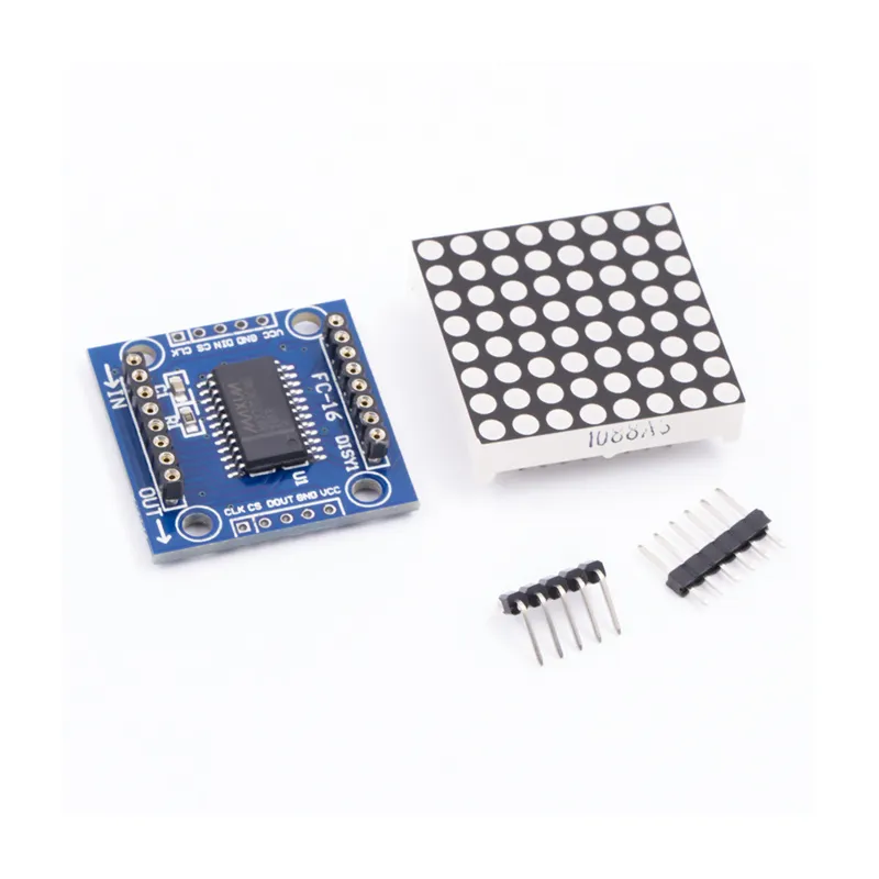
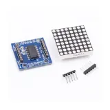
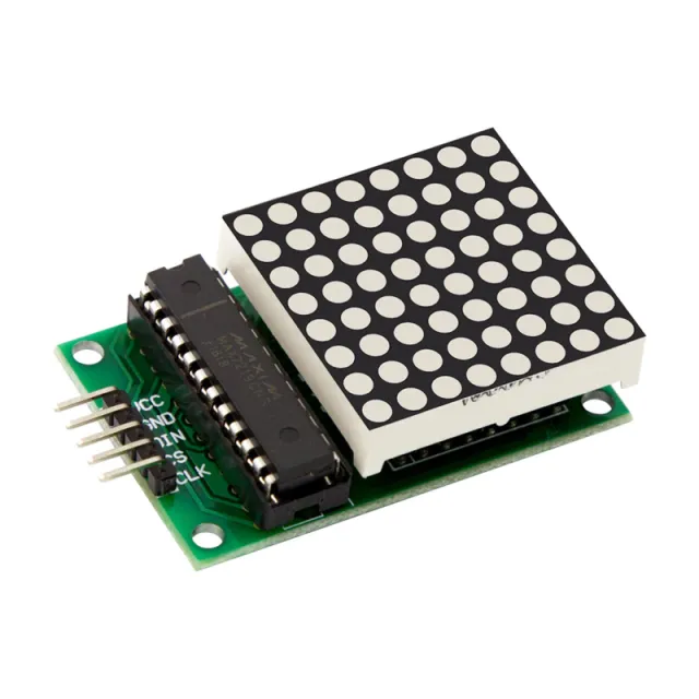
LED Matrix Modul MAX7219 Rot

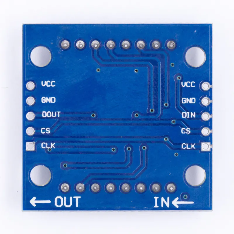
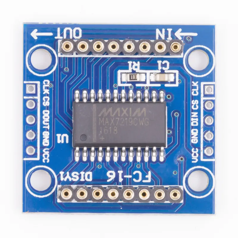
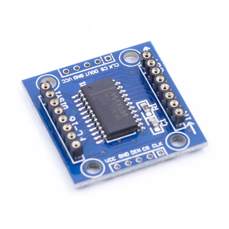
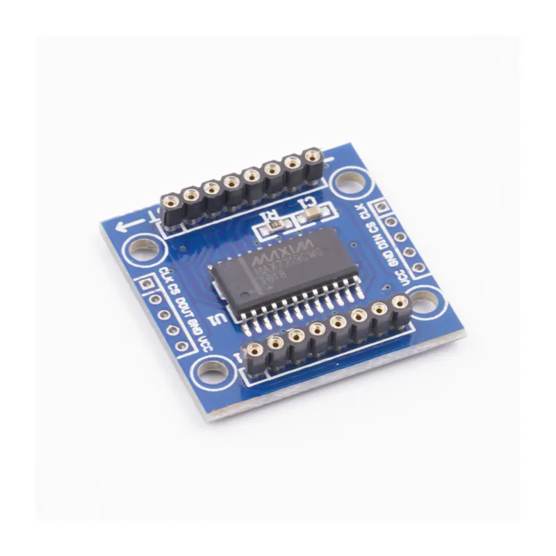
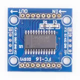
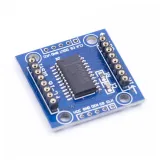
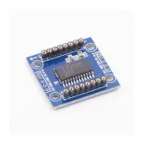
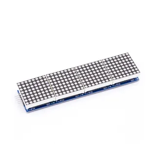
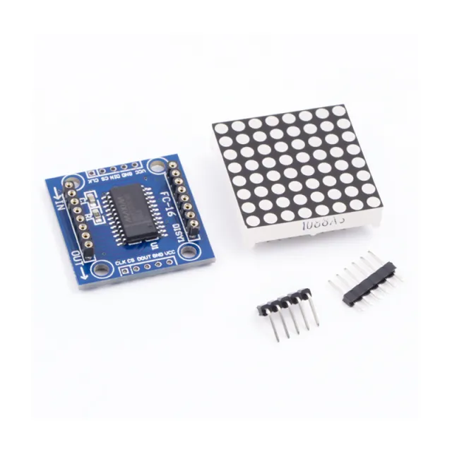
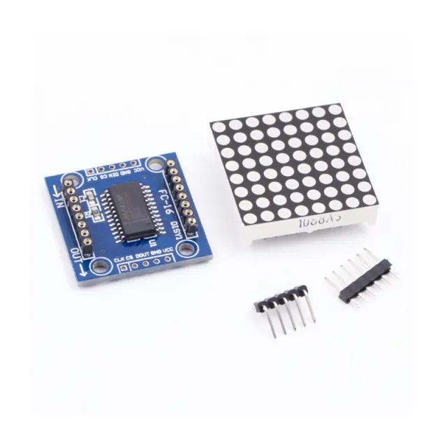
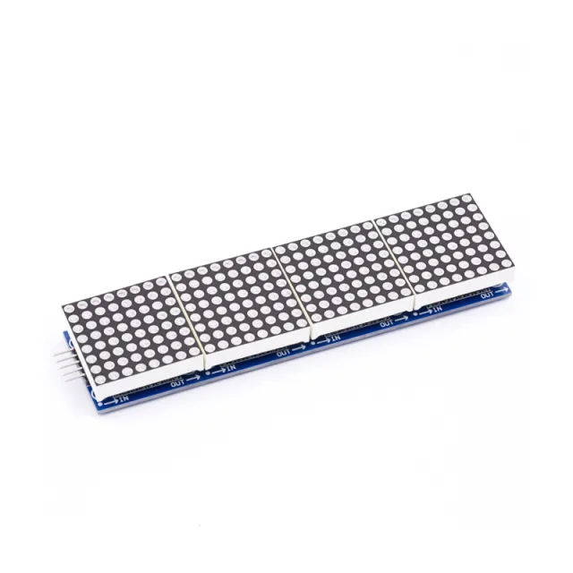
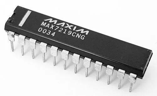
MAX7219 ist ein IC, das zur Ansteuerung von LED-Panels mit gemeinsamer Kathode, 7-Segment-Anzeigen und Pegelanzeigen verwendet wird, die über die SPI-Schnittstelle kommunizieren. Dieses Board hat ein 8x8 Dot-Matrix-LED-Display. Mehrere Module können mithilfe von Header-Verbindungen kaskadiert werden.

Spezifikationen:

  • 8x8 gemeinsames Kathoden-Display
  • Betriebsspannung: 5V
  • Betriebsstrom: 250mA (MAX)
  • Logikspannung der Schnittstelle: 5V
  • Schnittstellentyp: SPI
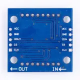
  • Anschlüsse: VCC, GND, DIN, CS, CLK
  • Kompatibilität: Kompatibel mit Arduino UNO R3 / Arduino Mega2560.
  • Bibliotheken für Arduino: Max72xxPanel und Adafruit_GFX
  • LED-Farbe: rot
  • LED-Größe: 5 mm
  • Anzahl kaskadierbarer Knoten: 32 (MAX)
  • Treiber-IC: MAX7219
  • Sehr geeignet für Arduino-DIY-Projekte
  • Abmessungen: 3,2 cm x 3,2 cm x 1,3 cm
  • 4x3 mm Befestigungslöcher
  • MAX7219-Treiber
  • 8x8-Matrix
  • SPI-Schnittstelle
  • 32 Module

Warum dieses Produkt wählen?

  • Geeignet für Arduino – Kompatibel mit UNO R3 und Mega2560.
  • Kaskadierbares Design – Mehrere Module können verbunden werden.
  • SPI-Schnittstelle – Funktioniert über die SPI-Verbindung.
  • Integrierte Bibliotheken – Unterstützt Max72xxPanel und Adafruit_GFX.
  • Rote LEDs – Matrixdisplay mit roter LED-Farbe.
Spezifikationen
Abmessungen3,2 cm x 3,2 cm x 1,3 cm
Betriebsspannung5V
KompatibilitätKompatibel mit Arduino UNO R3 / Arduino Mega2560
Treiber-ICMAX7219
Schnittstellenlogikspannung5V
SchnittstellentypSPI
AnschlüsseVCC, GND, DIN, CS, CLK
Arduino-BibliothekenMax72xxPanel und Adafruit_GFX
LED-Farberot
LED-Größe5 mm
Anzahl kaskadierbarer Knoten32 (MAX)
Befestigungslöcher4 x 3 mm
Arbeitsstrom250mA (MAX)

Bewertungen

★★★★★ 5,0/5 1 Bewertung
  • ★★★★★Martin vd V.

    Prima Produkt.

Bewertung schreiben
Deine Bewertung

Versand & Rücksendung

Versand

  • Paket mit Sendungsverfolgung€ 6,205 Werktage
  • Paket mit Sendungsverfolgung€ 7,455 Werktage
  • Paket mit Sendungsverfolgung€ 8,655 Werktage
  • Paket mit Sendungsverfolgung€ 9,255 Werktage
Alles zum Versand

Rücksendung

Nicht zufrieden? Du hast 30 Tage nach Erhalt Zeit, das Produkt zurückzusenden.

Alles zur Rücksendung

Zuletzt angesehen

Joystick-Modul

Joystick-Modul

€ 1,65